Welcome to the 12th tutorial on our series Mastering Forge.
In our previous article, Mastering Forge #11, we learned to configure Data Exchangers between nodes.
In this tutorial, we’ll go through two different use cases, both using the Modbus module. First, we will create a Modbus Device in Forge, which enables data to be received into Forge. Second, we will create a Modbus Server in Forge, which enables data to be provided from Forge. To complete this configuration, you’ll need to apply the skills learned in the previous article.
If you would prefer your tutorials in video format instead, you can watch our tutorial on how to configure Modbus connectivity with Forge on our YouTube channel.
During this tutorial, we’ll be using the following products:
- Prosys OPC UA Forge
- You can download an evaluation version through the request form.
- Prosys OPC UA Browser
- You can download the free version through the product’s request form.
- ModRSsim2
- You can download the free demo version from ModRSsim2’s download page.
- ModbusClientX
- You can download the free version from ModbusClientX’s download page.
Configure a Modbus Device
Typical Modbus devices include PLCs, I/O units, HMI panels, drives, and analyzers. In this demonstration, we use a simulator instead of a physical device.
Start the Modbus simulator (ModRSsim2). Use the default settings (port: 502, slave id: 1).
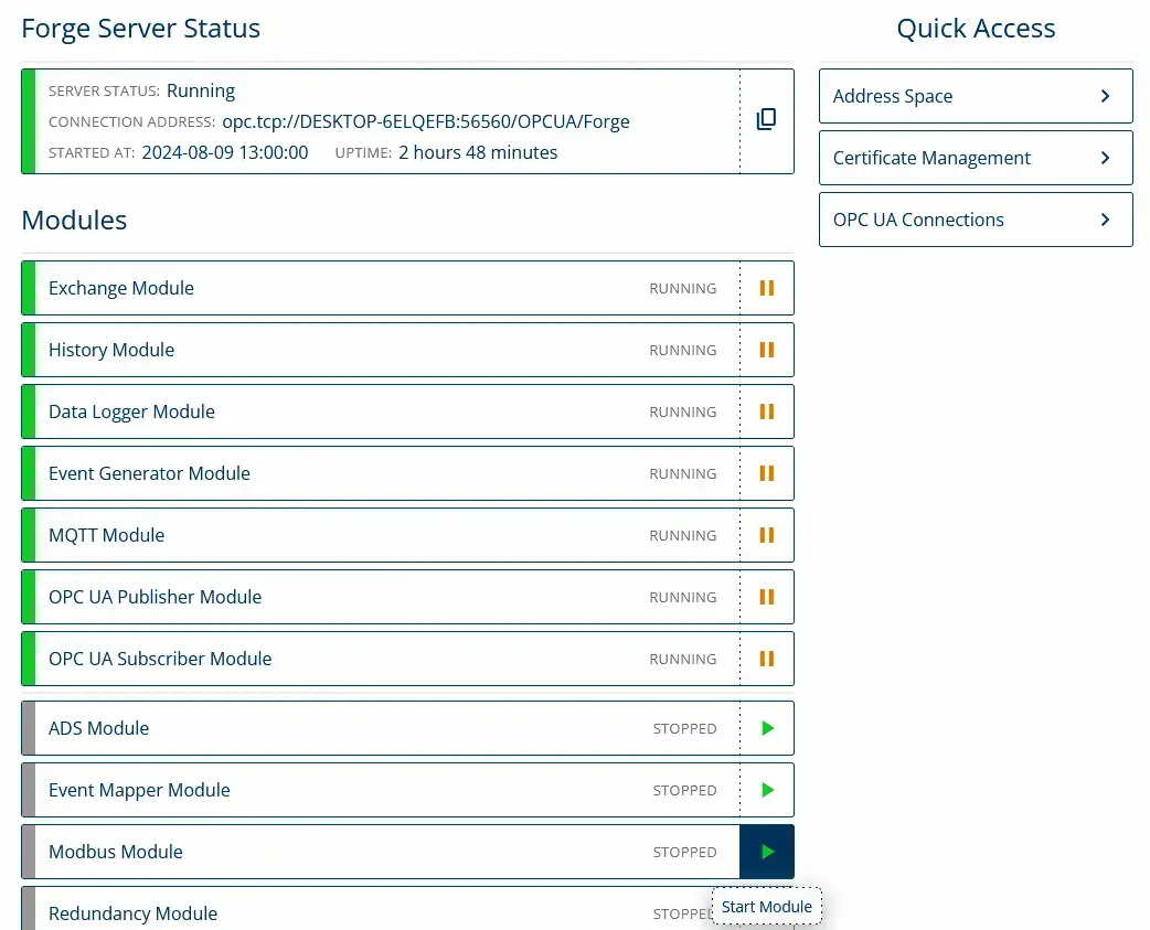
1. From the Dashboard, start the Modbus Module.
2. Navigate to Modbus > Modbus Devices and click + Add Device.

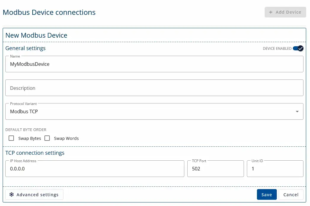
3. Give the Modbus device a name and set the IP Host Address to be 0.0.0.0. Keep the default settings TCP Port 502 and Unit ID 1 as in the Modbus simulator. Then, click Save.
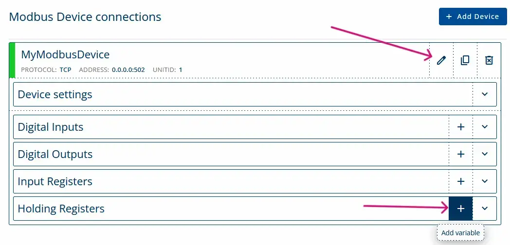
4. Next, configure the items with their respective Modbus addresses to enable data retrieval from the connected Modbus server. Click the edit icon and then + from the Holding Registers row.
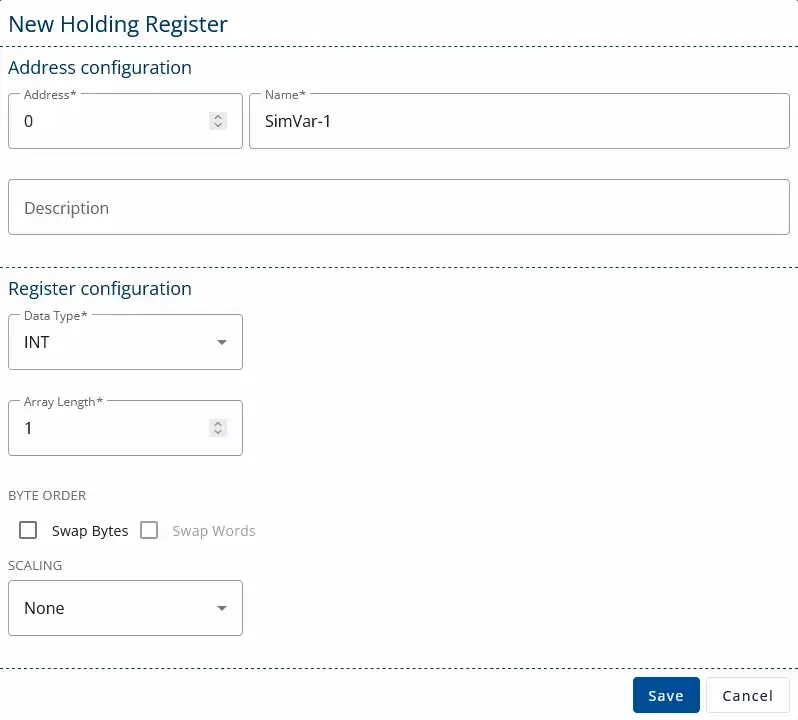
5. Address 0 contains a signal in our Modbus simulator. Assign a name to the item, retain the default settings, and click Save to finalize the configuration.
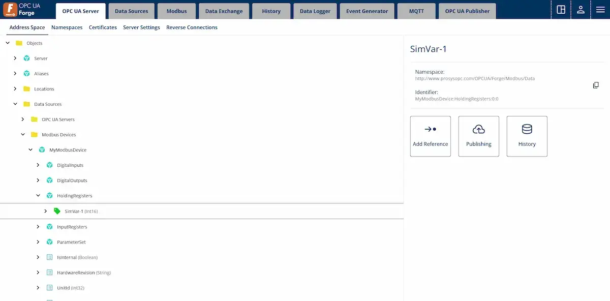
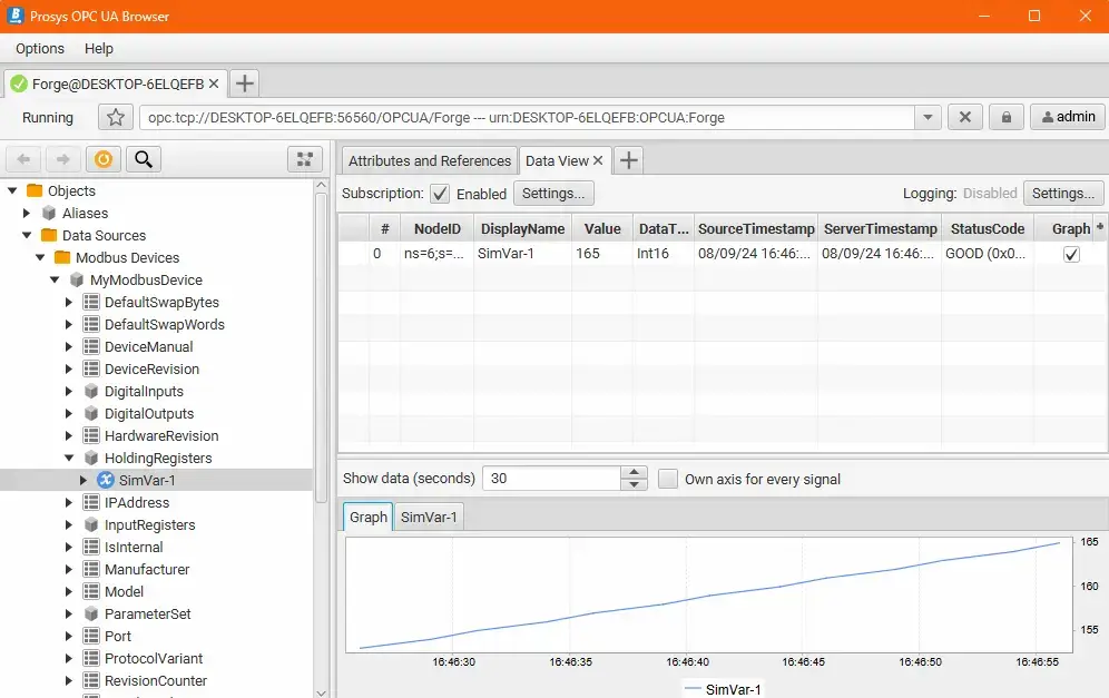
6. Finally, you can find the nodes from Forge’s address space from Objects > Data Sources > Modbus Devices > … for further configuration and use. You can also monitor the values with Prosys OPC UA Browser to verify that the data is received by Forge.
Configure a Modbus Server
For example, an HMI panel can have an embedded Modbus client, for which we would like to provide specific data from Forge. In this demonstration, we use Windows software called ModbusClientX instead of a physical device.
Close the ModRSsim2 to free the port 502. Ensure that the address space contains nodes with numeric values for use with the Forge’s Modbus Server.
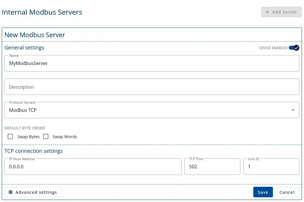
1. Navigate to Modbus > Modbus Server and click Add Server.

2. Give the Modbus server a name and set the IP Host Address to be 0.0.0.0. Keep the default settings and click Save.
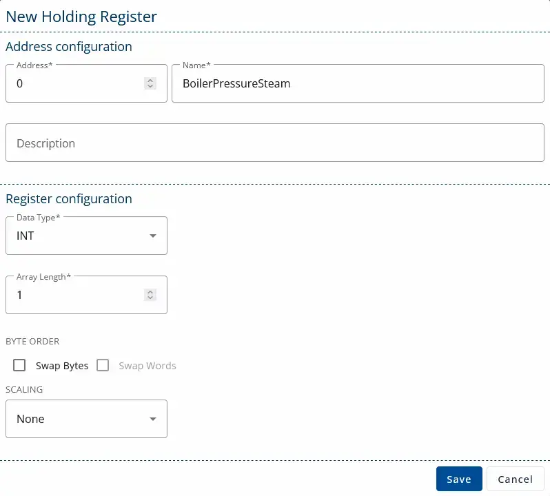
3. Next, we need to configure items into which we can map the data. The created items won’t have data immediately, but we will configure a Data Exchanger to write data into the Modbus items next.
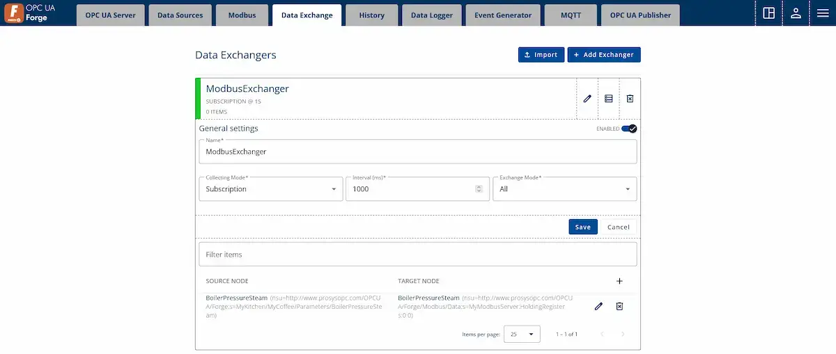
4. Create a Data Exchanger and exchange data from Forge nodes to the Data Sources > Modbus Server > MyModbusServer > HoldingRegisters… nodes.
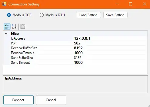
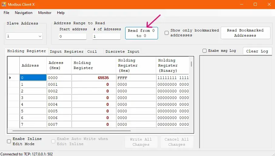
5. Now, you can receive the configured data with ModbusClientX by connecting it to Forge’s Modbus server and reading the previously configured registers.
Next Steps
This wraps up the 12th article of the Mastering Forge series. Here’s a recap of what we did in this tutorial:
- Created a Modbus device to receive data from a Modbus server.
- Created a Modbus server within Forge and configured a Data Exchanger to send data to the Modbus server’s registers.
- Used Prosys OPC UA Browser and ModbusClientX to verify the data flow.
In the next article, Mastering Forge #13, we will take a look at Forge’s OpenAPI documentation and how to authenticate and use it.
If you want to learn more about Forge and its capabilities, you can request a detailed introduction by emailing sales@prosysopc.com or using our contact form. We’d be delighted to provide tailored information about Forge that aligns with your interests and requirements.
Author Info

Iivo Yrjölä
Customer Integration & Support, Prosys OPC
Email: iivo.yrjola@prosysopc.com
